Description
GENERAL GUIDELINES:
- The equipment should be disconnected from power supply during wiring or in case of maintenance.
- Circuit breakers or main switch is recommended to install before equipment.
- Ensure proper input power cables and proper cable laying and cable clamping management done.
- The user strictly advised not to open the housing which will end the warranty.
- Use Press sleeves or lugged terminals to meet requirements and ensure that the screws are tightened.
- Do not touch the terminal when power is on.
- Follow the electrical wiring diagram for proper functioning of equipment. Wrong wiring will make device to malfunction and void the warranty.
OPERATION GUIDELINES:
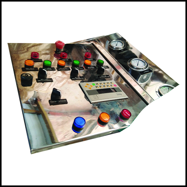
- QM-WLC-Eco controller package consists of 2 Float Switches and a controller. The pump tank should be installed with one float switch and the Overhead tank should be installed with another float switch.
- Both float switches are wired to the controller installed in the proper location (This equipment is not manufactured for outdoor purpose)
- QM-WLC-Eco controller can handle up to 2HP Single phase pumps also the same controller can be used with Starters for Submersible or 3phase pumps. (Please contact the manufacturer in case of you have 3Phase pumps or submersible pumps or higher ratings).
- Make proper wiring as per the Electrical wiring diagram instructed in this manual.
- Proper understanding of Float switches is a must because wrong calculation wiring length of float or improper fixing of float wires may lead to overflow or sump pump to dry run
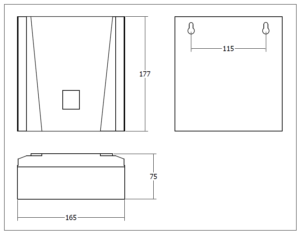
DIMENSIONS:
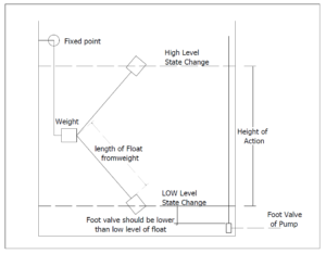
FLOAT WORKING PRINCIPLE:
FLOAT INSTALLATION GUIDELINES:
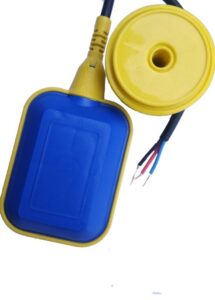
As per the name Cable Float Switch, it has 3 important parts,
- Body of the float – Where the NO/NC Element is molded and activated by a steel ball during the low and high levels of the tank.
- Weight – Weight plays an important role. The length between the weight and body of float determines Low and High Levels of the tank. Ensure weight should be fixed at distance from the body such that it should not move during operation.
- Wire – Wire should be fixed to the tank with help of Glands in case of PVC Tanks or through bolts and clamps in case of the civil tank. Wire length from a fixed point to weight is also important. Cable Float Switch has 3 wire common, NO, NC. Different manufacturers have different color codes. Floats supplied with QM-WLC-Eco will have wires as per below color code. (Subjected to changes in the future). Common – Black color wire.NC – Red Color wire at UP position.NO – Blue/Yellow Color wire at UP position. User need not worry about the NC & NO position and can simply follow the color code in the wiring diagram to ensure proper working.
TERMINAL CONNECTION:
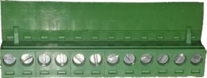
Important Note:
- Screw terminals should always face front. Wire feed at bottom. Wrong connection may not fit into connector. Forced wrong connection may damage the connector as well as equipment.
- Opening or Servicing of box/equipment will void the warranty. Contact manufacturer in terms of support or service.
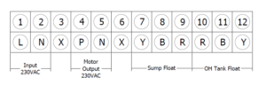
TERMINAL DESCRIPTION:
- L – Phase of Input Supply
- N – Neutral of Input Supply
- X – Dummy No Connection
- P – Phase output for pump
- N – Neutral output for pump
- X – Dummy No Connection
- Y – Yellow or Blue wire of Sump Float
- B – Black wire of Sump Float (Common)
- R – Red wire of sump Float
- R – Red wire of Over Head Tank Float
- B – Black wire of Over Head Tank Float (Common)
- Y – Yellow or Blue wire of Over Head Tank Float
CAUTION:
Read the Operating manual completely before installation and operation of the water level controller. Wiring & Installation should be made with the proper electrical technicians to avoid the risk of electrical shock. If safety procedures are not followed then the manufacturer does not have any liability for human or equipment safety.